Wednesday, June 5, 2013

My First Digispark Core Project - Blinking LED

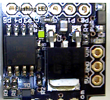
Digispark Flashing LED Shown In Green
     A previous blog entry detailed the contents of a new Arduino compatible microprocessor core with USB capability called Digispark.  The relatively small size of this platform along with capability for rudimentary USB connectivity without the need of any external components or boards makes this an attractive platform for PC interface projects.   This article will dive into a first implementation using the Digispark Core.

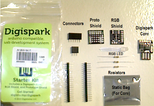
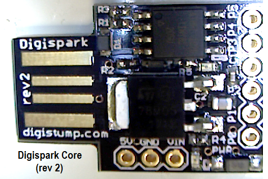
    In the world of software, a program that outputs "Hello World" is the usual first step to learning programming a new platform.  The "Hello World" in hardware development is often times to create a device that blinks an LED.  The Digispark Core has a single LED that can be controlled by an I/O pin.  Therefore, the goal is to setup the proper programming environment, compile the proper code, and transfer the blink firmware to the ATtiny85.

    First, the proper programming enviromnent should be installed on your platform.  The enviroment chosen was Windows, but Mac OSX and Linux are also supported.  Instructions were followed on the WIKI at: Digispark Software Installation.  A summary of steps for Windows is:

  1. Download latest Digispark customized Arduino environment.  Currently the latest shown on the WIKI is: Digispark Arduino Windows 32 Environment
  2. Unzip all contents to a target folder.  Be sure to leave the Digispark core unplugged from USB.
  3. From the target folder, locate the "...\DigisparkArduino-Win32\DigisparkWindowsDriver" and execute the "InstallDriver.exe" program.
  4. Start the Arduino programming environment located in the "...\DigisparkArduino-Win32\Digispark-Arduino-1.0.4" directory and run "Arduino.exe"
  5. Configure the Arduino environment for use with Digispark:
           a) Click on "Tools -> Board" and select "Digispark (Tiny Core)"
           b) Click on "Tools -> Programmer" and select "Digispark"
     Once these steps are followed, the proper environment will be installed and configured.  When running Arduino.exe, although a prompt to update the version was shown - we elected to ignore the update.

      Secondly, it was time to compile the first live program on the Digispark.  For this, under the "Arduino.exe" environment, click on "File -> Examples -> Digispark Examples -> Start".   This should load the LED blink code into the editor.

// the setup routine runs once when you press reset:
void setup() {               
  // initialize the digital pin as an output.
  pinMode(0, OUTPUT); //LED on Model B
  pinMode(1, OUTPUT); //LED on Model A  
}

// the loop routine runs over and over again forever:
void loop() {
  digitalWrite(0, HIGH);   // turn the LED on (HIGH is the voltage level)
  digitalWrite(1, HIGH);
  delay(1000);               // wait for a second
  digitalWrite(0, LOW);    // turn the LED off by making the voltage LOW
  digitalWrite(1, LOW);
  delay(1000);               // wait for a second
}


    In order to compile the code and transfer it to your Digispark, follow these steps:

  1. Make sure the Digispark core is not plugged into the USB port
  2. Under Arduino.exe, click on "File -> Upload".  Do not click on upload using programmer.  This will automatically compile the code.
  3. Notice the bottom of the Arduino window will show "Plug in device now... (will timeout in 60 seconds)".   It is important to quickly plug the Digispark core into the USB port quickly to avoid a timeout.
  4. When done correctly, your new code will be loaded and start running on the Digispark.
    Since the first programming was not clear if the original Digispark core from the factory was pre-loaded with the "Start" (blink) code, we decided to alter the firmware to present a faster frequency.  Changes to the original source are shown hilighted.

// the setup routine runs once when you press reset:
void setup() {               
  // initialize the digital pin as an output.
  pinMode(0, OUTPUT); //LED on Model B
  pinMode(1, OUTPUT); //LED on Model A  
}

// the loop routine runs over and over again forever:
void loop() {
  digitalWrite(0, HIGH);   // turn the LED on (HIGH is the voltage level)
  digitalWrite(1, HIGH);
  delay(250);              // Modification: wait 1/4 sec
  // delay(1000);             // wait for a second
  digitalWrite(0, LOW);    // turn the LED off by making the voltage LOW
  digitalWrite(1, LOW);
  delay(400);               // wait for nearly 1/2 sec  // delay(1000);              // wait for a second
}


     The result was a faster blink which proved programming over USB was working fine.  Now that the environment and process is complete, later projects can move on to more complex hardware and software implementations.  The next article will document use of the RGB shield.

Digispark Starter Kit Added to Jason Whiteman's Hardware Lab

Digispark Starter Kit from Jason Whiteman's lab in Houston, Texas
      June 4th, 2013 Jason Whiteman picked up a Digispark "Starter Kit" during his (nearly) weekly trip to MicroCenter in Houston, Texas.  The Digispark product is a smaller and less powerful Arduino-like open hardware platform in the form factor of a USB thumb drive without an outer case.  The Digispark core is comprised of USB gold-fingers for direct connection to a standard USB port, a voltage regulator (MC78M05 D-PAK), and the Atmel Tiny85 Microprocessor.


Digispark Core (2nd Revision) included in Starter Kit
Digispark RGB Shield resistors
      The Starter Kit also includes the an RGB Shield.  The RGB Shield includes an RGB LED (4 pin: GND, red +, green +, blue +), necessary current limiting resistors, a PCB for soldering the components, and necessary jumpers for interfacing the RGB shield to the Digispark core.

      The red LED is using the 180 ohm resistor in order to decrease the current through the red LED.  Both the green and blue LEDs have 100 ohm series resistors.  Assuming 5V I/O voltage, the red LED sees 23mA (milliamps) and both the green and blue LEDs see 43mA.   According to Ohm's law (V=IR), the smaller the resistor the larger the current.  Larger currents result in greater intensity (brightness) within the maximum current limits of the part.  According to the datasheet, the maximum allowed current is 100mA.

Digispark RGB Shield schematic and pin 1 identification of LED

      The final component is a Prototype Shield which is simply a small board with 40 through-hole connections (pads).  Of these 40 pads, 12 are dedicated to the bus between the core and the shield (6 pads are for jumper connector, and 6 pads paired with these 6 jumpers and left open for user connections), 2 pads are dedicated to VIN, 4 pads are dedicated to GND, and 4 pads are dedicated to 5V.  This leaves 18 pins for general use.

Digispark Prototype Shield showing pad assignments

      At MicroCenter, it is possible to save a dollar by purchasing the RGB shield and Digispark core separately.  However, I elected to purchase the Starter Kit in order to get the Prototype Shield.  Although it is unlikely I will actually use the prototype shield, the extra "tax" for including it was worth the charge.

      For more information, reference relevant datasheets.


Atmel Tiny85 (ATtiny85)

1. Atmel ATtiny85 Datasheet

2. ATtiny85 does not natively support USB.  Find out more about the USB implementation through software/firmware:
USB Implementation (Software)

Note: USB speed is low-speed mode (1.5 Mbit/s) of USB2.0

3. Complete list of documents for ATtiny85


4. The following datasheet, although perhaps not the exact manufacturer, matches the RGB LED used in the Digispark kit.  RGB LED Datasheet 

5. Although this blog has a hardware focus, in order to get started using the Digispark core, you will have to familiarize yourself with the software and PC interface.  All of this information can be found on the WIKI site: Digispark WIKI

      Good luck developing your own Digispark solutions.  Perhaps in the future, this blog will be updated with specific applications of the Digispark starter kit.